Monday, May 15, 2017

UAS Mission Plan in Tomah, WI

In the Field

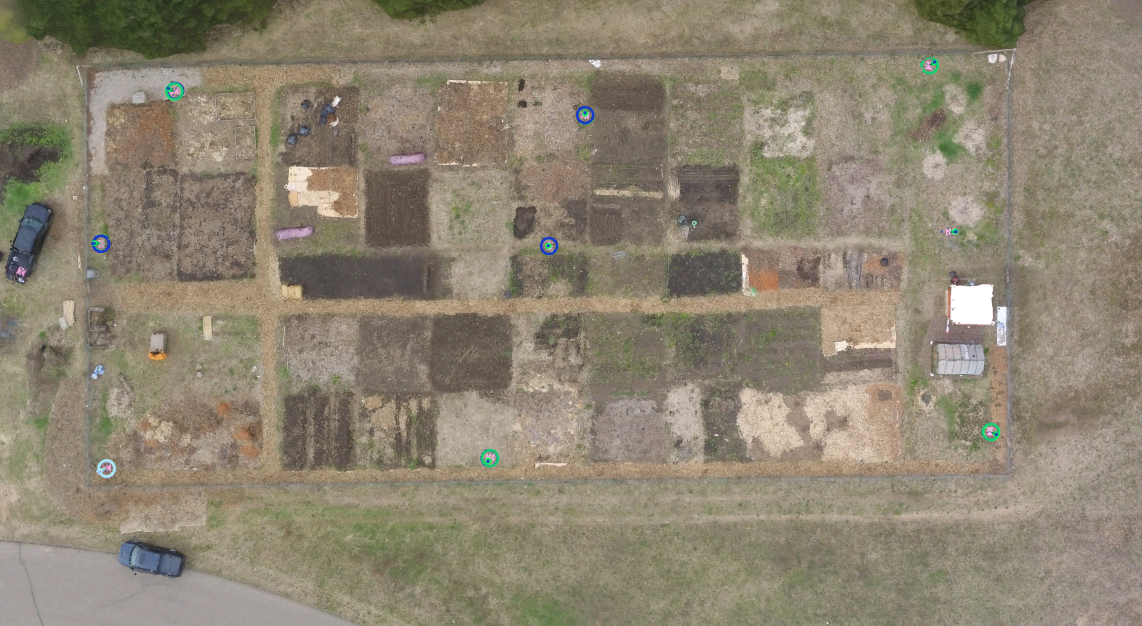
This week the students drove down to some wetlands in Tomah,Wisconsin. Here is where we met up with Peter Menet and the Trimble UX5. Very similar to last weeks lab we had set up the GCP's in the wetlands over a large area. Using the total station, accurate GPS coordinates were taken wherever a GCP was placed.

The first thing that was assembled for the fixed wing UX5 was the rail catapult launch system which extended to roughly 6 to 7 meters. The launch system had a crank and bungee that were used to allow the UX5 to be slung into the air before the motor took over.

Figure 1. UX5 setup and installation.

Following the setup of the launcher, preflight checklist and mission planning for the UX5 were put in place. The cool part about the UX5 and its software system that is already installed is that before you even fly, the program on the controller makes you go through a preflight checklist. Then you input certain parameters for the area you are flying and what type of conditions that you are in. The unfortunate part about this software is that there are no manual controls in case of an emergency you cannot just take over. After about a half an hour to forty minutes of preflight checking and mission planning the UX5 was ready for take-off. The launch was as easy as pressing a clamp and letting the program takeover once its in the air. The UX5 flew at roughly 55 mph and an altitude of 400 feet. When the mission was done for the UX5, it came in for the automatic landing and was extremely rough, but it lives to die another day.

Figure 2. UX5 launcher setup.

The next flight was with the M600 which was a multi-rotor with 6 propellers and had much larger dimensions. After the preflight checklist and the M600 was put together, and a mission plan was put together.

Figure 3. M600 being setup up.

Figure 4. M600 in midflight with the landing gear up.

Wednesday, May 10, 2017

UAS Mission Plan near South Middle School

In the Field

This week's project consisted of using our constructed GCP's and getting used to different UAS platforms at the community garden which is located near the South Middle School here in Eau Claire. First we took out 9 of the GCP's that were constructed and placed them in a grid pattern inside the garden area. We then used the Total Station to get accurate GPS points  as shown in figure 1. This is done by placing the Total Station directly in the middle of a GCP and obtain a level position for best accuracy of the GPS point.
Figure 1. Setting up the GCP and placing the correct GPS coordinates in the center of the GCP with the Total Station.


After the 9 GCP's were in place and had the GPS points established, a preflight checklist was being established with the DJI Phantom 3 Advanced. Part of the preflight checklist included drawing out a mission plan for the platform. There were various mission planning software on the tablet that could be utilized. Two flights with the Phantom 3 Advanced were performed with two separate plans. The first plan was flown at 70 meters over the community garden. The second flight performed was flown at 70 meters over the group of cars with an oblique camera angle of 75 degrees. After both of the mission plans were completed the Phantom automatically landed basically within 5 feet of where it took off.
Figure 2. Phantom 3 Advanced going through the preflight checklist before take-off.

The last flight conducted used the DJI Inspire which was also a multi-rotor that was slightly larger than the phantom 3 advanced. This flight did not have a mission plan to it as this platform was only used for the students to get an idea of how the platform performs. This included rotating, throttle up/down, and turning the platform. It was very smooth in its motions and seemed like it would be very hard to crash.
Figure 3. DJI Inspire assembled and ready for a preflight check.

Results
Figure 4. Oblique image of flight 1 processed data with GCP's calibrated to the images.


Figure 5. Plan view of flight 1 processed data.

Figure 6. Processed oblique imagery of vehicles during flight 2 with the angled camera and 3D modeling used in Pix4D.

Monday, May 1, 2017

Creating Ground Control Points (GCP's)


Ground control points (GCP's) are objects placed on the ground with specific locations in the area of interest so the processing and accuracy of UAS imagery can be increased on Pix4D. The GCP's that have been created will be used for the next couple projects.

Creating ground control points required a multiple stage process. The materials we used were cloth blankets for covering the cement, spray paint, plastic material about 1/4 inch thick, and a table saw. Of course all proper safety gear and equipment were used during the cutting process. First we had to cut the plastic material into squares using the table saw (figure 1).
Figure 1. Dr. Hupy and two students using the table to cut the plastic material into squares.

The next step was to use the pink spray paint and place a wood triangle stencil on the plastic material. The plastic squares were laid down on the cloth so the spray paint would not get on the floor. There was two triangles painted on opposite sides for each individual square. On the sides that were not spray painted with a pink triangle, a number was spray painted yellow to keep track of each individual GCP (figure 2).
No automatic alt text available.
Figure 2. The GCP's  that have been spray painted and completed for drying.

After all the GCP's were spray painted, we set them up against the wall for them to dry. Afterwards we discussed UAS related material in the shop.